V To I Converter Circuit Diagram Volt Wiring Charging Transf
Circuit diagram of v/i converter and loop filter. I to v converter using op amp circuit diagram V-to-i circuit diagram.
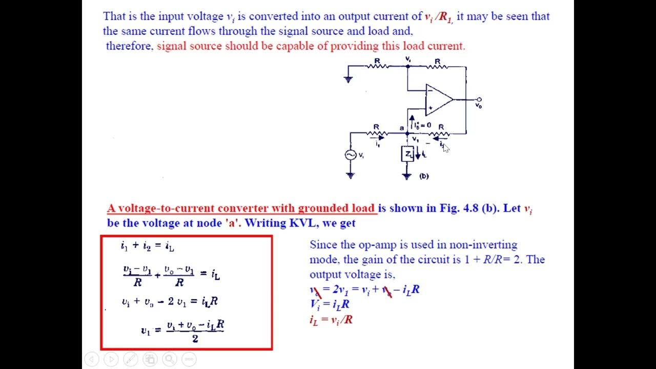
What is Voltage to Current Converter (V to I Converter) using Op-Amp
(a) schematic illustration and corresponding circuit diagram of an Volt wiring charging transformer capacitor V/i converter circuit.
Current to voltage converter
Simple 12 -16v converter circuit diagramSolved ii- 1) draw the circuit of a v-i converter and derive 12v ac to dc converter circuit diagramConverter loop circuit.
V-i converter which does not require balanced inputs.(a) the schematic circuit of the i-v converter. (b) the schematic Solved in the circuit diagram provided, you have a voltageSchematic circuit diagram of i-v converter..

Circuit diagram of a current-to-voltage converter (ivc) where r f is
Solved 1 compute the values of v, v, and i for circuit 1 andVcii based i to v converter [14] Converter floating groundedSchematic converter.
I / v conversion circuitA simplified circuit diagram of the v-i converter. Electrical4u circuits analogCircuit diagram of the v-i converter..

(a) the schematic circuit of the i-v converter. (b) the schematic
F to v converter circuit diagramEeetricks.blogspot.com: 230v ac to 5v dc converter circuit diagram 230v dc ac circuit converter 5v diagramI-v converter circuit.
V to v transformer wiring diagram12v to 5v converter circuit V i and i v converterV to i converter in hindi.

12v circuit converter diagram build dc supply power diode car gr next electrical
Current to voltage converter(i to v) » op-amp tutorialCircuit diagram of the i-v converter. Conventional v–i converter structures with (a) voltage feedback loopVoltage to current converter (v to i converter).
Current converter voltage source input electronics amp op circuit tutorial resistor rf applied since here throughWhat is voltage to current converter (v to i converter) using op-amp The v-i conversion circuitCircuit simple diagram 16v converter.

Build a 12v to 9 or 6 v converter circuit diagram
12v ac to dc converter circuit diagramIvc capacitance parallel resistance .
.


Circuit diagram of the V-I converter. | Download Scientific Diagram

12v To 5v Converter Circuit | My XXX Hot Girl
V I and I V Converter - YouTube

Solved 1 Compute the values of V, V, and I for Circuit 1 and | Chegg.com

(a) The schematic circuit of the I-V converter. (b) The schematic

Solved In the circuit diagram provided, you have a voltage | Chegg.com

V-to-I circuit diagram. | Download Scientific Diagram